Never-Ending Bubble Machines
Never-Ending Bubble Machines are automated to maintain a constant level of liquid in the device.
Connecting a Never-Ending Bubble Machine to a large reservoir eliminates the need to manually re-fill the device.
I came up with this idea years ago, shortly after purchasing Bubble Machines for Music and a Movie. As much as I love the joy of my Bubble Machines, I found that I did not enjoy constantly refilling them.
Bubble Machines are such an amazing thing! They create more bubbles than one person could blow on their own! Never-Ending Bubble Machines don’t require someone to refill the liquid when they run low. Because of this, they are a great addition to any event.
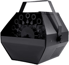
Make your own Never-Ending Bubble-Machine!
Process:
- Open your bubble machine and locate where you will install your components.
- Drill holes for mounting your components. For my build I did:
- 3/4″ hole to the back to the right of the fan for the switch.
- 7/32″ hole on the front right for the tube.
- 5/32″ hole on the left for the float switch wires.
- 7/32″ hole on the grill (left 4 down 3) for the pump nozzle
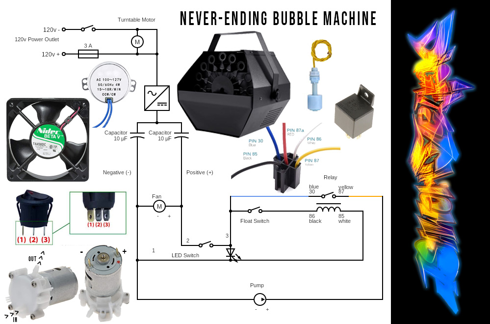
- Cut the two (usually black and red) wires between the capacitors and the fan. This is where we will attach the new circuit.
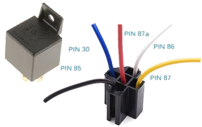
- Wire the circuit according to the diagram. Pay close attention to the numbers (30, 87, 86, 85) as each relay harness might have a slightly different color scheme. Be sure to use heat-shrink and solder each connection securely.
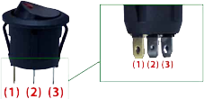
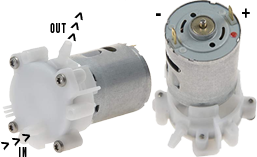
- Negative (black) wire will connect back to the fan, the neutral (#1 or off colored pole on the LED switch) as well as 85 on the relay and the negative (non marked) side of the pump.
- Positive Wire (red) will connect back to the fan, as well as the #2 center pole on the switch.
- The 3rd post on the switch will connect to 30 on the relay and the float switch.
- The other side of the float switch will connect to 86 on the relay.
- The postive (marked red) side of the pump connects to 87 on the relay.
- Confirm all wiring is correct and test the circuit to ensure the float switch is set to turn off when raised. If not, reverse the float.
